Just finished this project. The circuit actually works. The charge controller circuit can be found here: www.mdpub.com/555Controller using a 555 Timer.
If the economic argument for MPPT doesn’t stack up, perhaps it’s ability to match high voltage panels to a 12V battery will. Here I connect two 20W panels in…


26 comments
No ping yet
badphobar says:
December 12, 2014 at 1:08 am (UTC 0)
I think you only need the battery pack anti discharge diode as the
transisters will already as as diodes.
badphobar says:
December 12, 2014 at 1:21 am (UTC 0)
oh yah
use 10 cells and works great.
rey402 says:
December 12, 2014 at 2:19 am (UTC 0)
did You have the Diagram
rex pogi says:
December 12, 2014 at 2:21 am (UTC 0)
also did this circuit but mine does this weird buzzing sound before
recharging.
Ermin0s says:
December 12, 2014 at 2:47 am (UTC 0)
Im also making this controller, my question is, do you have all the
negative (ground) wires going to 1 place? and is the positive of you
battery going to the positive of the 5 volt regulator and resistors?
anthony christian Jaen says:
December 12, 2014 at 2:47 am (UTC 0)
also the diodes will also act like a resistor you used a smaller rectifier
diode with that dc current … you need to add higher amp diode and it will
also lower the voltage better use schotchky diode to minimize voltage step
down
Carol Liep says:
December 12, 2014 at 3:38 am (UTC 0)
How to set up the low and high charging volts for a 6 volts lead acid
batteries? For a 12 volts batteries the set up is 1.667 volts for low 11.9
volts and 3.333 volts for high 14.9 volts,right?
blahblah studios says:
December 12, 2014 at 3:40 am (UTC 0)
list the items
anthony christian Jaen says:
December 12, 2014 at 4:34 am (UTC 0)
sebwano ka man dong? accent mo bisaya
萧国庆 says:
December 12, 2014 at 5:18 am (UTC 0)
http://www.aliexpress.com/item/New-arrival-Bluetooth-4-0-anti-lost-alarm-for-Iphone-Ipad-Ipod/1807090006.html
Rajat Sharma says:
December 12, 2014 at 5:41 am (UTC 0)
Sir can you share the electric components that you used esp what is the
‘blue stuff’ on your video to control voltage…. Sorry I am completely
naive in electronics.
Aungkyaw Soe says:
December 12, 2014 at 6:19 am (UTC 0)
i sent.
Jacob Ellinger says:
December 12, 2014 at 6:37 am (UTC 0)
Would you be willing to help me with the list of parts I will need for a
project similar to this?
TheBudworth says:
December 12, 2014 at 7:04 am (UTC 0)
Nipples
Paul J. Wilson says:
December 12, 2014 at 7:10 am (UTC 0)
Brilliant!
Raymond Earle says:
December 12, 2014 at 7:18 am (UTC 0)
Excellent work sir.
HWman says:
December 12, 2014 at 7:26 am (UTC 0)
Мне нравится Ваш британский акцент.
joohop says:
December 12, 2014 at 8:07 am (UTC 0)
can i ask a favour julian ? just say i had 240v 1600rpm ac motor , now
theres two questions i here what size inverter would i need to comforyably
run it continuous ?
second quedtion – how would you with wires cheaply control the 12v input
from 0 to max slightly overbuilt ?
Arne Larsen says:
December 12, 2014 at 8:51 am (UTC 0)
Nice work.
But why are they in series?
i always believed that series gets the voltage op, and parralel gets the
watt op?
Daniel Smith says:
December 12, 2014 at 9:45 am (UTC 0)
This series of videos is awesome…am trying to do something similar for my
final year university project…but with automatic pwm adjustment/mppt
tracking.
Julian Ilett says:
December 12, 2014 at 9:57 am (UTC 0)
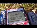
Solar Panel MPPT Test Rig #10 – 72 Cell Solar Panel charging 12V Battery
Julian Ilett says:
December 12, 2014 at 10:18 am (UTC 0)
And I think it’s time to put current and voltage sensors on the battery
side too, so both Watts in and Watts out can be measured. That will mean I
can put an efficiency percentage on the display. It’s one thing to extract
maximum power from the solar panel, but quite another to deliver it to the
battery without losing too much energy as heat.
James Wood says:
December 12, 2014 at 10:35 am (UTC 0)
What is the switching frequency? There seems to be a high pitched tone on
this video.
Julian Ilett says:
December 12, 2014 at 11:26 am (UTC 0)
15kHz, so you probably are hearing it.
xanataph says:
December 12, 2014 at 12:19 pm (UTC 0)
Looks like it’s coming along really well Julian.. 🙂 Do you think a brutal
approach for the inductor might work – i,e. just wind it with heavier wire?
Perhaps you could set up a line so you can send the power from those panels
indoors so you can have them connected and use the scope too.
Julian Ilett says:
December 12, 2014 at 12:59 pm (UTC 0)
Cheers! I think the hot inductor and the ringing are connected, so
hopefully it won’t be necessary to beef up the inductor too much. I’ve
bought 10 inductors from China, 100uH, supposedly rated at 6A. My
philosophy for this project will be easily available, low cost components,
so I’ll have to make it work with them. My main problem is lack of
sunshine, so I might put my 100W panel on the test rig and do some tests
under overcast skies.